The terms “earthing” and “bonding” get used interchangeably by people who don’t actually understand what either one does. On forums, in casual conversation, sometimes even by electricians who should know better, you’ll hear “earth bonding” as if it’s a single concept rather than two distinct protective measures with completely different purposes.
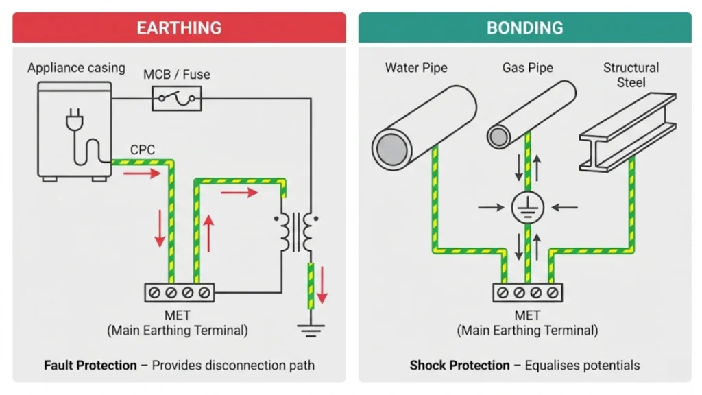
Here’s the fundamental distinction that every Level 2 learner needs to grasp before touching an installation: Earthing provides a low-impedance path for fault currents to operate protective devices. Bonding equalises potentials between simultaneously accessible conductive parts to prevent dangerous touch voltages. They’re not the same thing. They’re not interchangeable. You cannot bond an appliance casing (it must be earthed). You do not earth a water pipe (it must be bonded).
This confusion isn’t just academic. It causes real assessment failures. NVQ candidates who write “bonding carries fault current to trip the breaker” in their portfolios demonstrate they don’t understand protective measures under BS 7671. AM2 candidates who can’t distinguish exposed-conductive-parts from extraneous-conductive-parts make incorrect installation decisions that assessors spot immediately. Improvers on site who over-bond non-extraneous parts or miss genuinely extraneous metalwork create installations that fail EICRs.
The problem stems partly from how earthing and bonding are taught, often as procedures to follow rather than principles to understand. You learn “connect the green-and-yellow to the casing” without grasping why that casing needs earthing (to provide fault current path) versus why the nearby radiator needs bonding (to prevent it rising to a different potential during that fault). Both contribute to automatic disconnection of supply (ADS) under Chapter 41 of BS 7671, but they achieve safety through different mechanisms.
This article breaks down what earthing actually does, what bonding actually does, why BS 7671 treats them separately under different regulations, how they work together during faults, and where learners consistently get confused. No vague explanations about “safety” without specifics. No claims that one replaces the other. Just clear technical distinction supported by regulation references, so you can explain to an assessor (or a client) exactly why that motor casing gets earthed while that gas pipe gets bonded.
What Earthing Actually Does
Earthing exists to provide a deliberate, low-resistance path for fault currents to flow from exposed-conductive-parts back to the supply source, enabling protective devices (MCBs, fuses, RCDs) to operate quickly and disconnect the faulty circuit.
The mechanism:
When a fault occurs, let’s say a loose live conductor inside a washing machine touches the metal casing, current needs somewhere to flow. Without earthing, that casing sits at 230V waiting for someone to touch it and become the path to earth through their body. With proper earthing via the circuit protective conductor (CPC), that fault current flows through the low-impedance green-and-yellow conductor back to the main earthing terminal, through the earthing conductor to the means of earthing (earth electrode, supplier’s earth terminal), and ultimately back to the transformer.
The safety outcome:
The magnitude of fault current (typically hundreds of amperes in a properly earthed TN system) causes the protective device to operate within the disconnection times specified in BS 7671 Table 41.1. For final circuits not exceeding 32A, that’s 0.4 seconds maximum for TN systems. The circuit disconnects, removing the hazard before sustained contact causes injury.
What earthing does NOT do:
Earthing doesn’t prevent the fault happening. It doesn’t keep the casing at 0V during the fault (there’s always some voltage rise during fault current flow due to conductor resistance). It doesn’t equalise potentials between different metal work. That’s bonding’s job. And critically, earthing alone doesn’t protect you if you simultaneously touch the faulty appliance and a piece of extraneous metalwork at a different potential.
BS 7671 context:
Chapter 54 covers earthing arrangements and protective conductors. The regulations specify sizing requirements for circuit protective conductors (often using the adiabatic equation for short-circuit conditions), termination standards at the main earthing terminal, and earthing conductor requirements between the MET and the means of earthing.
Regulation 411.3.1.1 establishes that exposed-conductive-parts must be connected to the main earthing terminal via protective conductors. This is earthing. The intent is facilitating automatic disconnection, not potential equalisation.
Common misconception:
“Earthing sucks electricity away to the ground and that’s why you’re safe.” Not quite. In TN systems (the most common in the UK), fault current returns to the transformer via the earthing system, creating a circuit that allows high current to flow and trip the protective device. The “safety” comes from rapid disconnection, not from dumping current into the dirt.
What Bonding Actually Does
Bonding exists to create equipotential zones by connecting extraneous-conductive-parts to the main earthing terminal, ensuring these parts remain at substantially the same potential and preventing dangerous touch voltage differences between simultaneously accessible metalwork.
The mechanism:
Extraneous-conductive-parts (metal gas pipes, water services, structural steel, central heating pipework) can introduce earth potential into the building. During a fault elsewhere in the installation, or even under normal conditions with neutral-to-earth voltage in PME systems, these parts could sit at significantly different voltages than exposed-conductive-parts of the electrical installation.
Main protective bonding conductors connect these services to the main earthing terminal, typically where they enter the building. Supplementary bonding conductors create additional local equipotential zones in high-risk areas like bathrooms (Regulation 701.415.2) by connecting simultaneously accessible conductive parts (towel rails, metal baths, copper pipework, electric shower casings).
The safety outcome:
If you simultaneously touch a faulty appliance and a radiator, both connected through bonding to the same MET, they rise to the same voltage during the fault. No potential difference means no current flow through your body. The touch voltage (the voltage you experience) is minimized because bonding keeps everything at the same potential while earthing works to disconnect the circuit.
What bonding does NOT do:
Bonding doesn’t provide the primary fault current path. A bonding conductor might carry some current if there’s a potential difference between bonded parts, but it’s not designed or intended to carry the high fault currents that earthing conductors handle. Bonding alone cannot trip a protective device. And bonding doesn’t earth non-electrical metalwork. It connects it to the earthing system, which is different.
BS 7671 context:
Regulation 411.3.1.2 covers main protective bonding conductors connecting extraneous-conductive-parts to the main earthing terminal. Minimum sizing for TN-C-S (PME) systems is half the earthing conductor size, minimum 6mm², maximum 25mm² (unless calculation proves otherwise).
Regulation 701.415.2 addresses supplementary bonding in locations containing baths or showers. Critically, supplementary bonding may be omitted if all circuits are RCD-protected (30mA, rated to BS EN 61008 or BS EN 61009) and main protective bonding meets 411.3.1.2 requirements, but you must verify both conditions, not assume.
Common misconception:
“Bonding carries fault current to trip the MCB.” This confuses bonding’s purpose with earthing’s purpose. Bonding equalises potentials. During a fault, the earthing conductor carries the fault current. The bonding conductor might see some current if bonded parts are at different potentials, but that’s incidental to its primary function of potential equalisation, not its design purpose.
Exposed Parts vs Extraneous Parts: The Critical Distinction
The confusion between earthing and bonding stems largely from not understanding which parts get which treatment. The distinction is straightforward but absolutely fundamental.
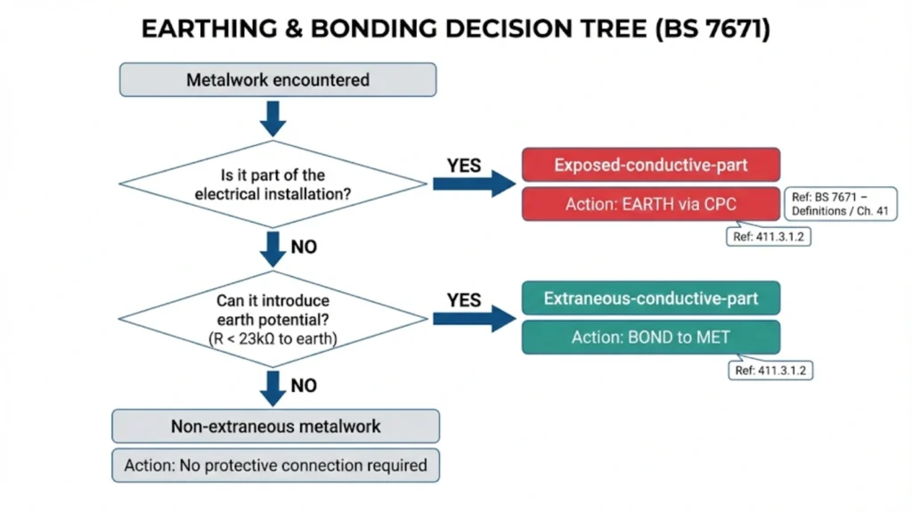
Exposed-conductive-parts (these get EARTHED):
These are conductive parts of electrical equipment that you can touch, which aren’t normally live but could become live under fault conditions. Metal appliance casings, consumer unit enclosures, metal light fittings, cable glands, conduit and trunking systems that form part of the electrical installation.
They’re part of the electrical system. When a fault occurs, they need a path for fault current to return to the source so protective devices operate. Hence: earthing via circuit protective conductors.
BS 7671 Part 2 defines them precisely: “Conductive part of equipment which can be touched and which is not normally live, but which can become live when basic insulation fails.”
Extraneous-conductive-parts (these get BONDED):
These are conductive parts NOT forming part of the electrical installation, but capable of introducing an earth potential. Incoming metal gas pipes, water services, oil supply pipes, structural steel, central heating pipework connected to a boiler with earthed metalwork.
They’re not part of the electrical system, but they can introduce potentials from outside or provide alternative earth paths. They need connecting to the MET to keep them at the same potential as the electrical installation. Hence: bonding via main protective bonding conductors.
BS 7671 Part 2 defines them: “Conductive part liable to introduce a potential, generally earth potential, and not forming part of the electrical installation.”
The test for extraneous parts:
Not sure if that copper pipe needs earthing or bonding? Use a multimeter set to resistance. Measure between the pipe and the main earthing terminal. If the resistance is 23 kΩ or less, it’s extraneous and needs bonding. If the resistance exceeds 23 kΩ, the pipe presents negligible risk of introducing earth potential and doesn’t require bonding under normal circumstances.
This test comes from GN8 and represents the resistance threshold above which the touch voltage would remain below 50V under fault conditions (safe touch voltage for general locations).
Common mistakes:
Treating structural steel as exposed-conductive-parts and running a CPC to it (it’s extraneous, it needs bonding via main bonding conductor, not a CPC)
Bonding isolated metalwork like a coat hook that tests above 23 kΩ (unnecessary and creates confusion during subsequent inspections)
Failing to bond genuinely extraneous parts like incoming gas because “it’s plastic at the meter” (if metal pipe enters the building, even if the meter is plastic, you bond the metal section within 600mm of entry)
Electricians who demonstrate clear understanding of exposed versus extraneous parts, and can explain bonding decisions with regulation references during site surveys, find that local courses teach bonding principles systematically rather than just teaching procedures.
Assessment implications:
AM2 candidates must demonstrate they can identify which parts require earthing versus bonding. Assessors specifically watch for incorrect terminology calling bonding conductors “earth wires” or claiming bonding “provides the earth” for services. These language mistakes reveal conceptual confusion that fails the assessment even if the physical work is correct.
How Earthing and Bonding Work Together During Faults
Neither earthing nor bonding works effectively alone. They’re the two halves of the protective measure known as automatic disconnection of supply (ADS) under BS 7671 Chapter 41.
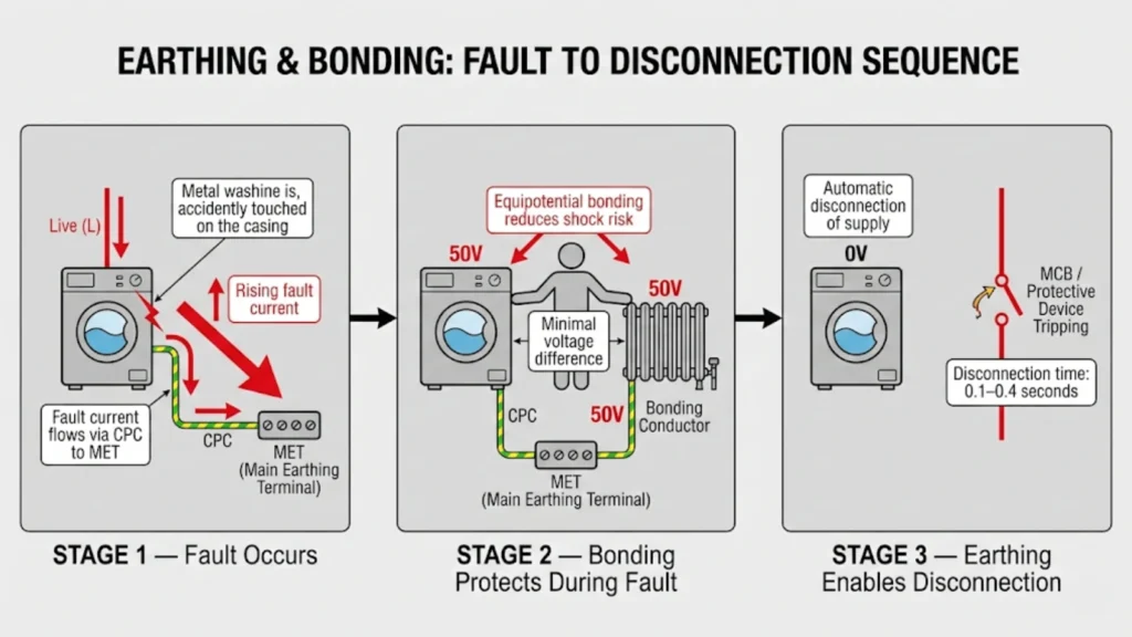
Fault scenario: Live conductor touches washing machine casing
Phase 1 (fault occurs, 0-0.4 seconds):
Live conductor contacts the metal casing. Without earthing, the casing sits at 230V. With proper earthing via the circuit protective conductor, fault current immediately begins flowing: live → fault point → casing → CPC → MET → earthing conductor → means of earthing → transformer. Current magnitude: potentially several hundred amperes in a TN-S system, thousands in a TN-C-S system depending on external earth fault loop impedance.
During these milliseconds, the casing voltage rises above earth potential due to voltage drop across the CPC resistance. This is where bonding becomes critical.
Phase 2 (bonding prevents side-flash during disconnection time):
The nearby radiator, connected to the central heating system fed from a gas boiler with earthed metalwork, is bonded via main protective bonding to the same MET. As the faulty washing machine casing rises to (say) 50V above true earth potential during fault current flow, the bonding conductor ensures the radiator rises to a similar potential.
Person touching both: Experiences minimal voltage difference because both parts are at substantially the same potential. Touch voltage is low. Current through body is negligible. Person waits (unknowingly) for the protective device to operate.
Phase 3 (protective device operates):
The fault current causes the MCB to trip magnetically or the fuse to blow, typically within 0.1-0.4 seconds for final circuits. Circuit disconnects. Hazard is removed. Person touching the faulty appliance and bonded radiator simultaneously experienced minimal shock because bonding kept both at the same potential during the fault.
Without earthing:
Fault current has no low-impedance path. The current magnitude is limited by contact with true earth through other available paths, often insufficient to operate protective devices. The faulty appliance remains live indefinitely. A person touching it completes the circuit through their body to earth, which may result in a potentially fatal electric shock.
Without bonding:
Fault current flows through the earthing conductor and the protective device operates. However, during the 0.1–0.4 second disconnection time, the faulty appliance casing may rise to 50 V above earth while the radiator remains at true earth potential. A person touching both simultaneously would be subjected to a 50 V potential difference, resulting in a dangerous shock current flowing through the body, even though the fault is cleared within the prescribed disconnection time.
The integrated protection:
Earthing ensures disconnection. Bonding ensures safety during the disconnection time. Both are required. Neither is optional in installations using automatic disconnection as the protective measure, which is essentially all standard UK installations under Regulation 411.3.
Supplementary Bonding: When It's Required and When It's Not
Supplementary bonding causes significant confusion, particularly in bathroom installations where regulations have evolved and many electricians learned outdated requirements.
What supplementary bonding is:
Additional local bonding connecting simultaneously accessible exposed-conductive-parts and extraneous-conductive-parts within special locations (primarily bathrooms and shower rooms under Section 701) to reduce touch voltage below main bonding alone.
It typically connects: metal baths, metal shower trays, central heating pipes and radiators, metal waste pipes, electric shower casings, heated towel rails, any structural metalwork within arm’s reach of bathing areas.
The modern omission criteria (Regulation 701.415.2):
Supplementary bonding in locations containing baths or showers may be omitted where:
- All circuits supplying the location have additional protection by RCD (rated residual operating current not exceeding 30mA and operating within 40ms at 150mA)
- All final circuits meet requirements of Regulation 411.3.1.2 for main protective bonding
Both conditions must be met. Not just RCDs. Not just assuming main bonding is correct. You verify:
RCD protection: Check the consumer unit. All circuits supplying the bathroom, including lighting, heating, shower circuits, and any socket outlets, must be protected by a 30 mA RCD. If the lighting circuit is connected to an older MCB without RCD protection, supplementary bonding cannot be omitted on that basis alone.
Main bonding adequacy: Visually inspect main bonding connections at gas and water entry points. Verify conductors meet sizing requirements (typically 10mm² minimum for TN-C-S, but depends on supply earthing conductor and system type). Check connections are tight and corrosion-free.
If either condition fails, supplementary bonding is required per 701.415.2.
When supplementary bonding IS definitely required:
Older installations without RCD protection: If circuits aren’t RCD-protected, supplementary bonding is mandatory regardless of main bonding quality.
Modified installations where RCD addition wasn’t possible: Sometimes main bonding is correct and you’d like to use the omission, but the consumer unit is old and RCD retrofitting isn’t economically viable for the client. Supplementary bonding provides the additional safety layer.
Special circumstances where resistance conditions aren’t met: Regulation 701.415.2 includes resistance criteria (R ≤ 50V/Ia) that can prevent omission even with RCDs. This is rare but possible in installations with poor earth fault loop impedance.
Common mistakes around supplementary bonding:
Assuming all modern bathrooms don’t need it: RCD protection is common now but not universal. Always verify rather than assume.
Not bonding because “everything’s plastic”: Supplementary bonding connects EXPOSED parts (shower casings, towel rail elements) to EXTRANEOUS parts (copper pipes, radiators). Even if waste pipes are plastic, you’re still creating equipotential between electrical equipment and heating system.
Bonding plastic-backed towel rails: If the towel rail has no metal connection to the heating system (plastic pipe connections, plastic backing plate), it’s not extraneous. Check continuity before bonding.
Incorrect conductor sizing: Supplementary bonding conductors are sized differently from main bonding. Minimum 4mm² if mechanically protected, 6mm² if not (Table 54.8). Learners sometimes use 2.5mm² thinking it’s adequate.
Assessment traps:
AM2 candidates must demonstrate understanding of when supplementary bonding can be omitted. Assessors ask directly, “Can you omit supplementary bonding in this scenario?” The correct answer requires checking RCD presence and verifying main bonding quality, not just saying “yes, there’s an RCD.” The regulation requires both conditions.
Plastic Pipes and the "No Bonding Needed" Myth
The shift toward plastic plumbing created a widespread myth: “Plastic pipes mean no bonding required.” This is partially true but dangerously oversimplified.
The principle:
Extraneous-conductive-parts are metalwork capable of introducing earth potential. If incoming water service is entirely plastic from the meter to all taps, with no metal sections and no earth path, then technically it’s not extraneous and bonding isn’t required.
Why “plastic pipes = no bonding” is still wrong:
Metal still exists somewhere: Even with plastic incoming supply, there’s often a metal stopcock at the boundary, metal sections under the floor, or metal fittings where appliances connect. These create earth paths that make the system extraneous.
Boilers and heating systems: Central heating systems almost always contain metal components, including boilers with earthed electrical parts, copper pipework within the boiler, and metal radiators throughout the property. The heating system may constitute an extraneous-conductive-part even if the cold water supply is plastic.
Gas services remain: Plastic water doesn’t affect gas bonding requirements. If there’s a metal gas pipe entering the building, it requires main protective bonding regardless of what the water pipes are made from.
Oil supplies: Oil-fired heating requires bonding of metal oil supply pipes entering the building. Again, unaffected by water pipe material.
Structural steel: If the building contains structural steelwork with an earth path (common in modern construction), it requires bonding regardless of plumbing materials.
The test remains essential:
Do not assume that plastic pipework means no bonding is required. Measure the resistance to earth. If metal sections are present and the resistance is below 23 kΩ, the system is considered extraneous and requires bonding. If it genuinely exceeds 23 kΩ across all accessible metalwork, which is unlikely but possible, bonding is not required.
EICR implications:
Coders who mark “C2 – Absence of main bonding to water supply” on installations with entirely plastic water services make incorrect observations. The water supply isn’t extraneous if there’s no metal introducing earth potential. This damages professional credibility when reviewed.
Conversely, coders who see plastic incoming supply and assume NO bonding is required anywhere might miss extraneous heating systems, gas services, or structural steel that absolutely require bonding. Both over-coding and under-coding stem from not testing what’s actually extraneous.
The practical approach:
Visual inspection: Trace services from entry point through the building. Look for metal sections, metal valves, copper inserts in plastic fittings.
Resistance testing: Where uncertainty exists, test resistance between questionable metalwork and the MET. Above 23 kΩ, not extraneous. Below 23 kΩ, likely extraneous and requires bonding.
Apply regulation requirements:
If it’s genuinely not extraneous (plastic throughout, no earth path, resistance test confirms), bonding isn’t required per Regulation 411.3.1.2. If any metal provides earth path, bonding is required.
Client communication:
When clients question bonding on mixed systems, explain the principle: “We’re bonding the metal sections that can introduce earth potential, not the plastic sections that can’t. Even though your cold water is plastic, your heating system contains metal components with earth paths, so bonding is required there.”
This is more credible than “regulations say we have to” without explaining why.
Common Assessment Failures and Site Errors
Understanding earthing versus bonding conceptually matters more than memorizing procedures, because assessments test understanding and site conditions require judgment.
NVQ Level 3 portfolio failures:
Terminology errors: Writing “bonding provides earth for the gas pipe” or “main bonding carries fault current.” These statements reveal that you do not understand the distinction. Bonding does not provide an earth; it connects extraneous-conductive-parts to the earthing system. Bonding is not intended to carry fault current as its design purpose; that function is performed by protective conductors and earthing conductors.
Incorrect part identification:
Describing a metal appliance casing as extraneous (it’s exposed). Claiming a plastic-backed radiator requires bonding (it’s not extraneous if isolated). Failing to identify structural steel as extraneous (it absolutely is if it has earth connection).
Missing regulation justification:
Claiming supplementary bonding isn’t required because “there’s an RCD” without referencing Regulation 701.415.2 or verifying main bonding compliance. Assessors need to see you understand the regulation, not just the outcome.
AM2/AM2E practical assessment failures:
Wrong conductor sizing: Using circuit protective conductor sizing methods (adiabatic equation, Table 54.7) for bonding conductors. Main bonding in TN-C-S is sized from the neutral conductor per Regulation 544.1.1, not from the circuit line conductor. Supplementary bonding uses Table 54.8.
Inadequate testing: Failing to verify bonding effectiveness through resistance testing. Simply connecting a bonding conductor does not prove equipotential conditions; you must measure and confirm that the resistance between bonded parts is acceptably low.
Incorrect supplementary bonding omission: Omitting supplementary bonding in a bathroom with RCD protection but not verifying that main bonding meets 411.3.1.2 requirements. Both conditions must be checked.
Over-bonding demonstration: Bonding every radiator individually when they’re all connected through a system already bonded at the boiler. This shows you don’t understand what makes something extraneous (earth path introduction, not just being metal).
EICR coding errors:
C2 coding plastic services: Marking absence of bonding to plastic water supply as “Potentially Dangerous” when the supply isn’t actually extraneous. This creates unnecessary remedial work and questions your competence.
Missing genuinely extraneous parts: Failing to identify and code missing bonding to structural steel, oil pipes, or metal gas services because you assumed plastic water meant no bonding anywhere.
Incorrect supplementary bonding observations: Coding bathrooms for missing supplementary bonding without checking whether omission is permitted under 701.415.2 (RCD protection + adequate main bonding).
Over-reliance on labels: Assuming bonding is adequate because “Safety Electrical Connection” labels exist, without testing bonding continuity or verifying connections are tight and effective.
Site installation errors:
Creating parallel earth paths: Over-bonding creates multiple parallel paths that can cause problems in fault conditions, particularly in TT systems where current might divide unpredictably.
Exporting earth potentials: Bonding conductive parts that extend outside the equipotential zone (metal fencing connected to structural steel, for example) can export dangerous potentials beyond the protected area.
Inadequate connections: Using connectors not suitable for the conductor size, making connections on painted surfaces without removing paint for metal-to-metal contact, or inadequate mechanical strength allowing connections to work loose.
Understanding these distinctions separates electricians who command confidence from those who struggle with inspection work, and regional rates vary with capabilities. Inspectors who consistently demonstrate earthing and bonding competence typically earn 15-20% more than those who over-code or under-code due to conceptual confusion.
How to avoid these failures:
Learn the principles, not just the procedures: Understand WHY exposed parts get earthed (fault current path) and WHY extraneous parts get bonded (potential equalisation). The “how” follows naturally from the “why.”
Test, don’t assume: If uncertain whether something is extraneous, test resistance to earth. If unsure bonding is effective, measure resistance between bonded parts.
Reference regulations correctly: When justifying decisions (in portfolios, in client discussions, in assessment interviews), cite specific regulations. “Regulation 411.3.1.2 requires main bonding” is more credible than “the regs say.”
Distinguish terminology precisely: Earth. Bond. Exposed. Extraneous. These aren’t interchangeable words. Using correct terms demonstrates understanding.
How This Applies to Modern Installations
Earthing and bonding principles remain constant, but modern installations introduce additional considerations that require applying fundamental understanding rather than following outdated procedures.
EV charger installations:
Electric vehicle chargers require careful earthing the charger casing is an exposed conductive part that must be connected via the circuit protective conductor. In outdoor installations, the mounting post or wall bracket might be extraneous if it has an earth path through structural elements, requiring bonding.
The expansion of EV infrastructure means electricians comfortable with earthing and bonding distinctions are better positioned for emerging work, though policy changes affect specialization demands and market uncertainties require electricians to maintain broad competence across installation types rather than over-specializing too early.
TN-C-S supply systems (PME) create specific considerations for EV chargers. The IET Code of Practice for EV charging addresses earthing arrangements and bonding requirements that differ slightly from standard final circuits. Understanding exposed versus extraneous parts becomes critical when determining what requires additional protection.
Solar PV installations:
Photovoltaic systems introduce exposed-conductive-parts (inverter casings, mounting frames if accessible, DC isolators) that require earthing. Mounting systems on metal roofs might introduce extraneous-conductive-parts requiring bonding if the roof structure has an earth path.
Amendment 2 to BS 7671:2018 modified requirements for protective bonding of solar PV systems, particularly around DC side arrangements. The fundamental principles remain: earth exposed parts for fault protection, bond extraneous parts for potential equalisation, but application requires understanding what’s exposed versus extraneous in PV-specific contexts.
Heat pump installations:
Air source and ground source heat pumps contain electrical components (compressors, control systems) with exposed-conductive-parts requiring earthing. External units often have metal casings that must be connected via the circuit protective conductor.
Ground source systems introduce additional considerations because the ground loop pipework may be extraneous if it provides an earth path through the ground. The installation is classified as an outdoor electrical installation under Section 714, which has specific earthing and bonding requirements.
Smart home and IoT integration:
Modern homes contain numerous low-voltage electronic systems, such as smart thermostats, lighting controllers, and security systems. These can still incorporate exposed-conductive-parts, including metal faceplates and control enclosures, which require appropriate earthing where necessary, even if the operating voltage is low.
Confusion sometimes arises when installers assume low-voltage equipment doesn’t need earthing. The principle remains: if it’s an exposed-conductive-part of electrical equipment, it requires connection to the protective conductor regardless of normal operating voltage. Fault protection requirements don’t disappear just because the device usually operates at 12V or 24V.
Consumer unit evolution:
Metal consumer units became mandatory under Amendment 3 (originally Amendment 2 proposal) to BS 7671:2018. The metal enclosure is an exposed-conductive-part requiring earthing. Many electricians correctly earth the enclosure via the incoming earthing conductor but miss that the enclosure itself must be bonded to the internal earthing bar, not just mechanically attached.
The distinction: the enclosure is exposed (part of the electrical installation) and must be earthed for fault protection. Any structural metalwork the consumer unit is mounted to might be extraneous (not part of electrical installation but capable of introducing potentials) and would require separate bonding.
Testing and verification technology:
Modern multifunction testers measure earth fault loop impedance, RCD performance, and insulation resistance, all of which depend on correct earthing and bonding arrangements. A sound understanding of the underlying principles is essential to accurately interpret test results and verify compliance.
For example, unexpectedly low earth fault loop impedance might indicate unintentional parallel earth paths (over-bonding). Unexpectedly high readings might indicate poor earthing or bonding connections. You can’t interpret results competently without understanding what earthing and bonding are meant to achieve.
The constant principle:
Technology changes. Installation types evolve. Regulations get amended. But the fundamental distinction remains: earthing provides fault current paths for automatic disconnection, bonding equalises potentials to prevent touch voltage hazards. Apply this understanding to whatever installation type you encounter, and the specific requirements become logical rather than arbitrary rules to memorize.
What This Means for Your Training
Earthing and bonding aren’t variations of the same thing. They’re distinct protective measures that work together to create the safety system we call automatic disconnection of supply under BS 7671 Chapter 41.
Earthing (Chapter 54, Regulation 411.3.1.1):
Bonding (Regulation 411.3.1.2, Section 701):
Why the distinction matters practically:
When you’re on site deciding what to connect where, you need to ask: “Is this part of the electrical installation (exposed) or is it introducing potential from outside (extraneous)?” The answer determines whether you earth it (via CPC) or bond it (via bonding conductor).
When you’re doing an EICR, you need to assess whether earthing provides adequate fault protection AND whether bonding creates effective equipotential zones. Missing either protective measure is a deficiency, but they’re different deficiencies requiring different remedial approaches.
When you’re explaining to a client why their gas pipe has a green-and-yellow conductor attached, “it’s required” is weak. “This bonding conductor keeps your gas pipe at the same electrical potential as your electrical system, preventing dangerous voltage differences if a fault occurs elsewhere in the house” demonstrates understanding.
When you’re sitting an AM2 assessment, the assessor isn’t just checking you can physically install conductors, they’re verifying you understand the principles behind automatic disconnection of supply. That requires distinguishing earthing’s role (fault current path) from bonding’s role (potential equalisation).
Call us on 0330 822 5337 to discuss electrical training pathways that actually prepare you for site work. We’ll explain exactly what you need, how long it takes, and what our in-house recruitment team can do to secure your first placement. No hype. No unrealistic promises. Just practical guidance from people who’ve placed hundreds of learners with UK contractors.
FAQs